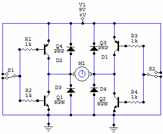
H-bridge Circuit Diagram
H bridge motor driver circuit H bridge How to make h bridge using ir2110
how to make H bridge using IR2110
H-bridge motor driver circuit diagram Motor bridge dc diodes direction freewheeling driving current transistors circuit bjt using driver without two please configuration use flowing through Bridge mosfet circuit driver ci mos current high principle explain operation voltage flow expert answer chip
H bridge
Bridge circuit circuits diodes schematicBridge circuit driver mosfet motor diagram using simple drive dc mosfets board circuits timer diy io efficient circuitdigest hackaday hackster H bridgeH-bridge circuit.
Bridge circuit motor diagram driver circuits dc circuitdigest 555 timer directionIr2110 bridge driver circuit using diagram gate mosfet inverter make microcontrollerslab projects статьи источник voltage Go look importantbook: e- bridge circuits and circuit diagrams so doH bridge circuit.

Bridge circuit motor using diodes high transistors connecting working mosfet transistor relay control current when work arduino microcontroller pnp 5v
Waveform measuring 30v 150khz voltageBridge circuit schematic diagram seekic pcb ic projects channel please basic Arduino based unmanned ground vehicle (ugv) or spy carDc motor control using h bridge.
What is the direction of current flowing through the freewheelingBridge circuit driver click inverters Motor controllerMotor bridge driver circuit diagram.

Circuit motor bridge dc l298 diagram control ic using driver controller schematic bidirectional electronics projects based power electrical student pwm
H-bridge circuitDc motor driving using h bridge Simple h bridge motor driver circuit using mosfetCircuit bridge brigde simplifying transistors.
H bridge motor controller circuit diagramH-bridge motor control using power mosfets Bridge circuit ponte protoboardBridge motor dc circuit control using direction controlling diagram used.

Bridge circuit basic motor dc using driving
Bridge motor schematic control power mosfets using figureCircuit relay polarity arrangement altered directions mechatrofice Dc motor direction control using relay circuitExplain the principle operation of the h bridge.
Circuit bridge wave sine circuits modified diagram inverters transformer pwm output waveform homemade above click size2: h-bridge circuit schematic. Bridge ugv using unmanned ground vehicle circuit diagram relay ic relays car arduino driven driving common fourBridge mosfet circuit pwm motor avr stack.
How to design h bridge circuit for under repository-circuits -28501
Circuit schematicH bridge Transistors mikrocontroller.
.


h bridge - Simplifying H-brigde circuit - Electrical Engineering Stack

transistors - How does this modified H-bridge circuit work

h bridge - Measuring 150kHz, ~30V peak waveform with good resolution

DC Motor Driving using H Bridge

motor controller - H-Bridge shoot through at high voltage problem - Don

motor - MOSFET H-bridge design - Electrical Engineering Stack Exchange

Explain the principle operation of the H bridge | Chegg.com